TMS-RGB → Development Story
Acknowledgements
I'm Nicholas Piegdon (Falonn at AtariAge) and I built and investigated each of the solutions detailed in the timeline below, designed the TMS-RGB circuit, and laid out the initial, v1 PCB.
The AtariAge community in the "ColecoVision / Adam" sub-forum was very helpful and encouraging throughout the process, but I would be remiss not to mention ChildOfCv specifically. Without his patient help and guidance every step of the way, this project would have never gotten off the ground, let alone been completed.
After my v1 PCB layout, MrPix from AtariAge spent countless hours working back-and-forth, teaching me the ways of board design while guiding me to improve hundreds of small layout details. This effort culminated in the v2 PCB.
Finally, Ruggers Customs was kind enough to put a few v2 boards through their paces across his extensive collection of different Colecovision hardware revisions. He tested dozens of combinations of output jack, different cables, and hardware revisions to make sure this was truly a universal solution.
Thank you everyone!
The Problem
Our story begins with why this is a challenging problem. Many retro consoles output an RGB signal or something close to it natively. The Colecovision (or any system that uses the TMS992xA) does not. It almost outputs a standard component video (or YPbPr) signal, with two important differences: first the output levels of each channel are a little different, but much more importantly, the chip also outputs a small voltage bump called a "colorburst" during each horizontal blanking interval.
That last detail is curious because colorbursts are for composite video (and eventually RF), not component! Having the VDP generate the colorburst is a convenience for the video output styles of the day but makes it trickier for component or RGB video.
It may be that older (or higher quality?) RGB equipment does things differently, but modern equipment that accepts an RGB signal uses the same horizontal blanking period to decide on the black level for all three channels. Because the red and blue outputs are doing something different than showing black during this time, the receiver measures the wrong minimum levels. The red line (with a positive colorburst) is always too weak and the blue line (with a negative colorburst) is always too strong. This means that even black appears on screen as a strong blue color.
Defeating this too-much-blue effect has been the objective of many projects over decades.
The datasheet describes that only the PAL version of the chip (the TMS9929A) is supposed to emit a colorburst on the blue and red lines. This is an error. The NTSC version of the chip (the TMS9928A) also emits a colorburst on (only) the blue line.
Design Timeline
1980'ish – TMS9928/29 and TMS9128/29 Interface to Color Monitors is a document released by Texas Instruments with a detailed description and circuit design for RGB output. I've annotated the document to highlight known errors. (Original here.)
- The good: the two-page write-up gives a lot of insight into each of the steps necessary during the conversion.
- The bad: it contains several errors and missing component values. The circuit requires tuning with an oscilloscope. It also makes no attempt at solving the too-much-blue problem.
1982 – Baby Pac-Man is an arcade game that used the TMS9928A. The repair manual contained a complete schematic, including the video interface for output to the RGB arcade monitor. It appears to be based on the Texas Instruments document with most of the functional blocks (DC restoration, sync separator, clock generator, and composite output) removed.
- The good: It worked for that arcade unit...
- The bad: It also made no attempt to fix the too-much-blue problem. Presumably the arcade monitor used a different means (factory calibration?) to assess the black level, so there was no reason to go to the trouble of removing the colorburst pulses. It also required oscilloscope tuning.
2015 – Yurkie from AtariAge begins selling a proprietary RGB mod designed by juice2839 from AtariAge. From reports, this mod also sometimes suffered from the too-much-blue problem. When photos of the mod eventually surfaced it appeared to be based on the Baby Pac-Man design (though this has never been confirmed to the best of my knowledge).
2016 – Alexis Kotlowy's TMS9929A RGB and Component adapter at Hackaday was designed for the PAL version of the chip, where the colorbursts are documented and cannot be ignored. It's the first known TMS-specific circuit to use a clever sample and hold technique for suppressing the colorburst pulses.
- The good: Finally, something can defeat the too-much-blue problem! It also dropped the oscilloscope tuning for a fixed color conversion matrix, making installation one step easier.
- The bad: Besides using a part that was unfortunately discontinued the following year, it suffered from a couple other minor problems. These included poor color accuracy, some color smearing, and output capacitors that aren't large enough.
2018 – Citrus3000psi's ColecoRGB was designed in response to Yurkie's proprietary mod. This one also appears to be based on Baby Pac-Man and suffers all the same problems. Citrus' real contribution here was the smaller form factor that allows soldering the whole thing right onto the back of the VDP, making installation almost trivial.
Around the same time, Citrus3000psi also released a ColecoRGB PAL board that appears to be a verbatim copy (with a couple errors and no attribution that I've ever seen) of Alexis' circuit from Hackaday. Again, the innovation here was shrinking the board to a DIP-40 footprint.
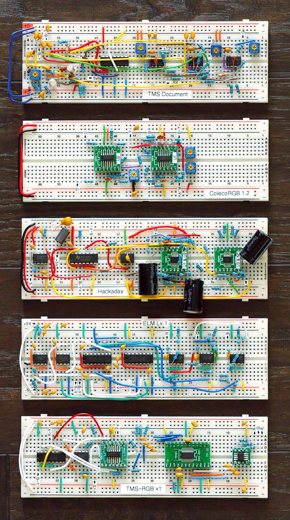
March 2020 – I begin building the circuits from the Texas Instruments document, from Hackday, and ColecoRGB to test and characterize the behavior of each, providing my source for all the above comments.
April 2020 – With more investigation into color accuracy, more testing with the sample-and-hold in the Alexis' circuit, and some fresh ideas from a non-TMS992xA-specific YPbPr-to-RGB conversion circuit, the rough outline of what would become TMS-RGB started taking shape. Problems still included a lot of noise, colors that still needed to be worked out, and the threat of needing to include a programmed microcontroller which would add a new hurdle to board assembly.
May 2020 – Trying one more experiment with a kind of all-in-one YPbPr-to-RGB chip made by Texas Instruments called the LMH1251 defeated every remaining problem simultaneously and dropped the part count considerably. The microcontroller programming requirement was gone. Color conversion (now handled almost completely by the chip) was much more accurate. And the noise was completely cleaned up. After some final wrap-up, the image was looking excellent. Too-much-blue was now defeated.
TMS-RGB was informed by every past design: the insight and color conversion formulas from the Texas Instruments document, the sample-and-hold idea from Alexis' Hackaday circuit, and the idea of the small form factor from ColecoRGB. Other ideas came from the ELM circuit mentioned above along with the idea to try out the LMH1251 that I learned about from a blog post about the RetroTINK COMP2RGB.
Alternatives to RGB
Briefly, it's worth mentioning that while RGB gives incredibly clean, emulator-like output, there are a couple alternatives:
The F18A and F18A-MK2 VDP is an FPGA-based drop-in replacement for the original TMS99x8A family of chips. In addition to offering clean RGB/VGA output, it adds new features like the elimination of sprite flickering.
The CollectorVision Phoenix console is another FPGA-based replacement project, but it doesn't stop with the VDP: it's a complete console that's compatible with your original Colecovision game cartridges.