TMS-RGB → Connection Diagrams
Why More than One Choice?
By the time the RGB signal reaches your receiver, every signal should be standard "75Ω video, 0.7Vpp". But there are a lot of different cables and adapters out there because the output from most retro consoles is anything but standardized. TMS-RGB is rather flexible when it comes to trying to match the output of another system (like the Sega Genesis model 2) so you can use any existing cables you might already have.
This page is going to focus on two configurations—"plain" 8-pin mini DIN and "Genesis 2" 9-pin mini DIN—but many other configurations are possible. These two are convenient because they're both small, round connectors that are the easiest to fit in place of the RF jack or to only drill a single hole in your case. And cables are readily available for both configurations.
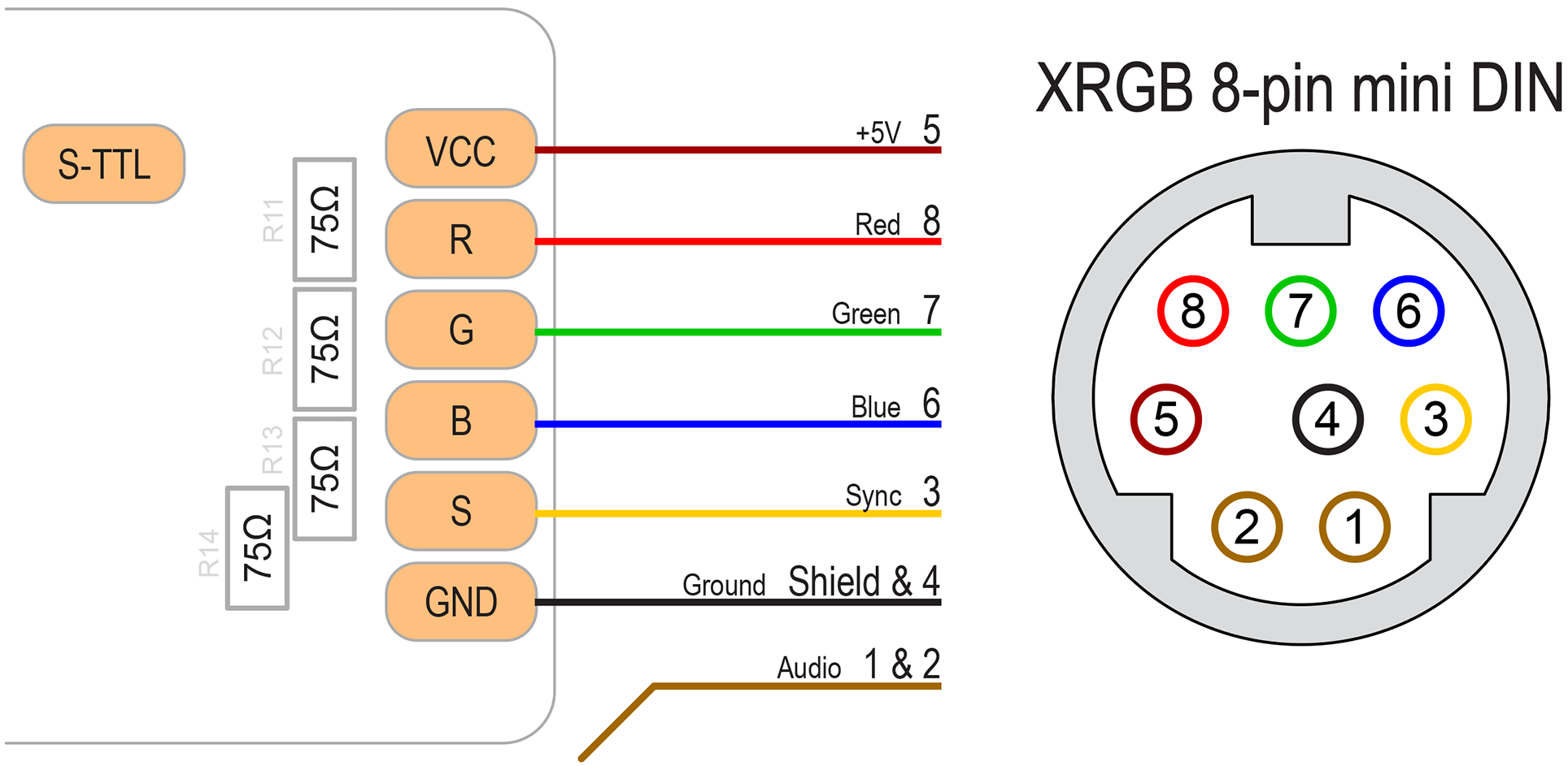
XRGB 8-pin mini DIN
This is less of an official standard and more a connection style that the retro gaming community has adopted as a kind of de facto standard instead. The idea is to have the console itself output everything already at the correct levels for SCART or BNC RGB video so that the cable can be a direct pass-through with no components. This might be considered the "purest" solution and TMS-RGB was designed to use this style by default.

Compatible cables: from Retro Access (in the US) or Retro Gaming Cables (in the UK).
Those cables will get you as far as a SCART connection. From there you can use your favorite upscaler or line-doubler like the OSSC or Framemeister.
In this case the board contains all the necessary 75Ω resistors and the TTL-level sync pad isn't used.
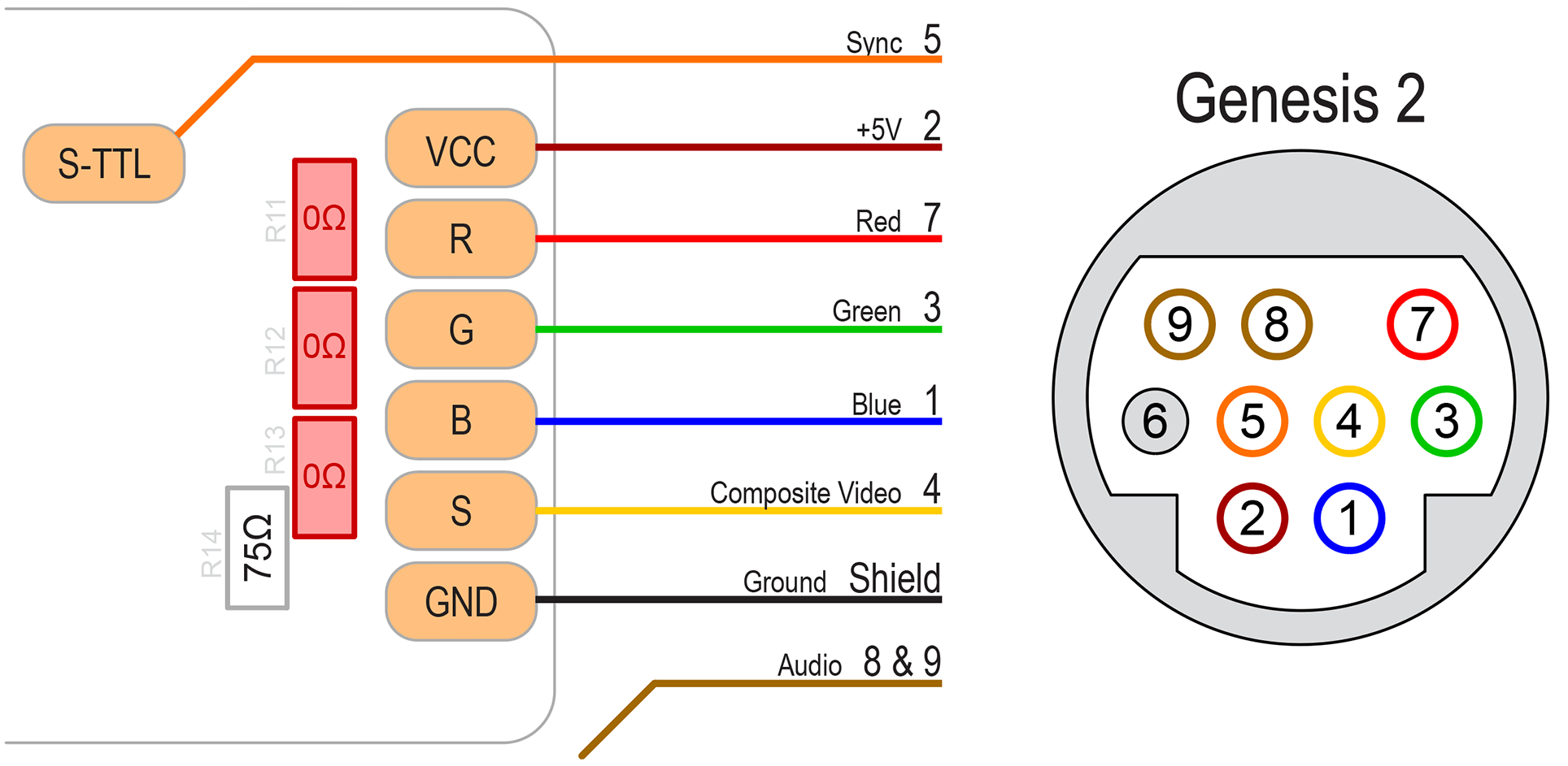
Genesis Model 2
The connector used by the Sega Genesis (or Mega Drive) Model 2 is rather popular and has at least one additional thing going for it: it can also carry a composite video signal. If your system is also modded for composite video, you can run that to pin 4 on the jack (instead of using the S pad on TMS-RGB) and then you'll be able to use either RGB or Composite Video cables for the Genesis Model 2. So, it's more flexible in that way, even if things are a little less ideal with the components in the cable rather distant from the circuit board.
We make both sync connections—video-level sync to pin 4 and TTL-level sync to pin 5—because different cables and adapters are known to use one or the other.
R11, R12, and R13 have been replaced here with 0Ω jumpers (or a bit of wire or a solder bridge) as the cable itself should contain the 75Ω resistors instead. If you don't omit the 75Ω resistors on the board, your video will be rather dark.

Compatible cables and adapters:
- Retro Gaming Cables Genesis 2 RAD2X: this adapter converts directly to HDMI, so you don't need any other equipment.
- Retro Gaming Cables Genesis 2 RGB SCART cable.
- Retro Access Genesis 2 SCART cable with CSYNC.
- Insurrection Industries Genesis 2 SCART cable.
Avoid the HD Retrovision "Genesis YPbPr Component" cable. It contains active circuitry that seems to digitize and enhance the noise on the line, making it impossible to clean it up later from your television. During testing colors also appeared incorrect.
Other Connections
To have TMS-RGB impersonate other consoles (so you can use cables designed for them), you just need to follow a few general rules. You may notice a pattern in the following:
- If the original console outputs a 5V "TTL" level sync signal, connect that pin to the "TTL" pad on TMS-RGB. The cable should contain a 300 to 500-ohm resistor on that pin.
- If the original console didn't have any output resistors on the R, G, and B lines, make sure to use 0-ohm jumpers for R11, R12, and R13. The cable should contain 75-ohm resistors on those pins.
- If the original console did have any output resistors, make sure to use 75-ohms for R11, R12, and R13. The cable shouldn't have resistors on those pins.
- If your cable expects "composite video", use the "S" pad. If the cable contains a 75-ohm resistor, R14 can be 0-ohm. If not, R14 should be 75-ohm.
- Really, just make sure there's 75-ohms somewhere between R11-14 and your receiver. If your cable has it, TMS-RGB doesn't need it. If the cable doesn't (and the pad is used), TMS-RGB does.
- Some consoles output +12V through their jack. If you're installing this in a Colecovision, +12V is available, so you should be able to impersonate those consoles, too, by tapping from the +12V power rail!